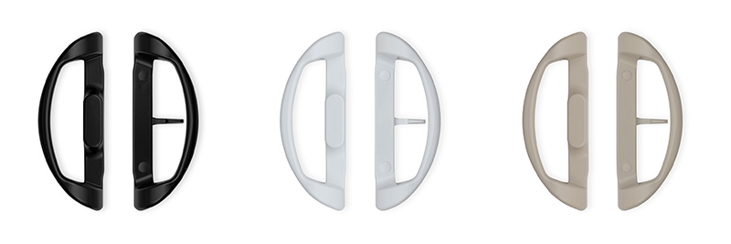
How to Install the Patio Glass Door 82-030 Adaptable Handle Set
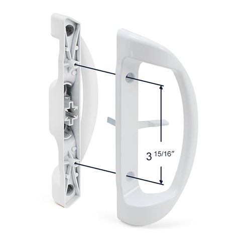
With its ability to accommodate a variety of different locking lever and key lock positions, the 82-030 is among SWISCO’s most versatile handle sets with 3-15/16” hole spacing. This article details the installation of this product.
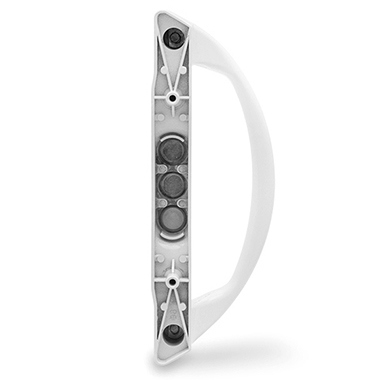
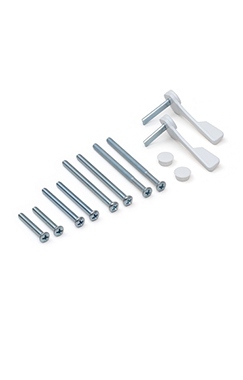
This handle set includes various installation screws to fit doors that are between 1” and 2-¼” thick. Included are four pairs of #8-32 machine screws with varying lengths, as well as two locking levers with different spindle lengths, one with a 1” spindle and another with a shorter ¾” spindle.
This handle set comes with a cross insert used to brace the outside handle for extra security when no key lock is installed.
INSTALLING THE HANDLE SET
The first step to install this handle set is to attach the locking lever through the door to the mortise lock. Then, place the inside pull on top so that it aligns with the screw hole centers.
Note that the 82-030 is designed to accept a locking lever either in the center position of the handle set--that is to say, perfectly centered between the screw holes--or in an offset position lower or higher on the base.
Be sure that the lock lever works correctly before you attach the handle to the door. If it doesn't, you may need to try again and make sure you are inserting the locking lever’s spindle into the mortise lock correctly, or that your mortise lock is not damaged.
With one hand securing the inside handle, align the outside pull with the screw holes. After the outside handle is aligned, place the #8-32 machine screws through the door. Then, fasten the two pulls together using a Phillips head screwdriver. If necessary, we recommend getting a second person to help hold the handle set in place during this process. You may cover the screw heads with caps that come included with this product.
INSTALLING A KEY LOCK
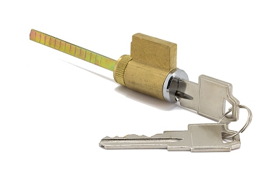
The 82-030 can be adapted to use a key lock like our 82-310. The outside pull features an extrusion with three punchouts on its inner surface. The 82-030 is also offered with a preinstalled key lock and lever fixed in the centered or offset position. See the 82-030A and 82-030B.
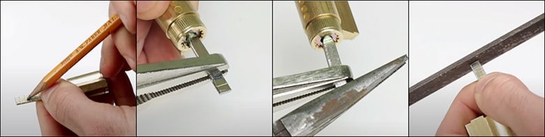
To install a key lock, you will need to remove one of these punchouts. We recommend using a center punch tool.
The three punchouts are meant to be used for the different possible alignments of the outside handle and the mortise lock. Be sure to remove only the punch-out hole that aligns with the position of the keyway in the door.
If you choose to use a key lock, you will need to remove the cross insert that is normally used to brace the outside handle.
Once you have knocked out the correct punchout, insert the key cylinder so that the tailpiece fits into the mortise lock. You may need to cut the tailpiece with pliers if it interferes with the spindle of the lock lever on the inside pull.
If you have any further questions regarding this handle set or any other products, please contact our team of experts at SWISCO’s discussion board.

