How to Install the 40-214 Security Door Lever Mortise Lock Set
A step-by-step tutorial for installing a Security Door Mortise Lock Set on a storm door.
Note: Before installing the 40-214, determine that the latch bolt is in the correct position. See instructions and Diagram 1 below for reference.
Step 1
Slide the lock housing into the door frame, making sure that the radius of the latch bolt is in the
correct position.
Step 2
Using pre-drilled holes in both the top and bottom of the lock housing as a guide, determine the proper
location and drill two, 1/8″ diameter holes into the door frame. Secure the lock housing to the door
frame using two of the supplied #8 self-tapping screws (A) – Diagram 3.
Do not over-tighten screws, this may cause the threads to strip.
Step 3
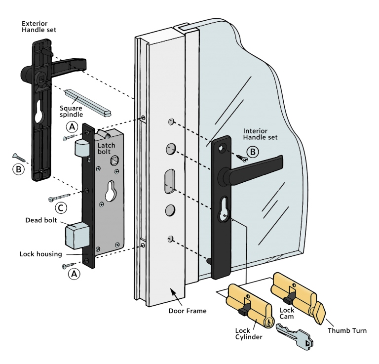
Position the inside handle on the door and insert the square spindle through the door and lock housing.
Position into the outside handle.
Step 4
Position the inside handle on the other end of the square spindle. Loosely fasten the inside and outside
handles together using one of the provided #8 self-tapping screws (B) – Diagram
3
Some movement of handles is necessary in order to complete step 5.
Step 5
Turn the lock cam to the up position by inserting the key, if you have a double-keyed locking cylinder,
or thumb turn if you have a thumb turn and key locking cylinder. Slide the lock cylinder through the
handles and lock housing. Secure the lock cylinder with the supplied brass machine screw (C)- Diagram 3.
Check to make sure the lock functions then tighten the screws inside and outside.
Step 6
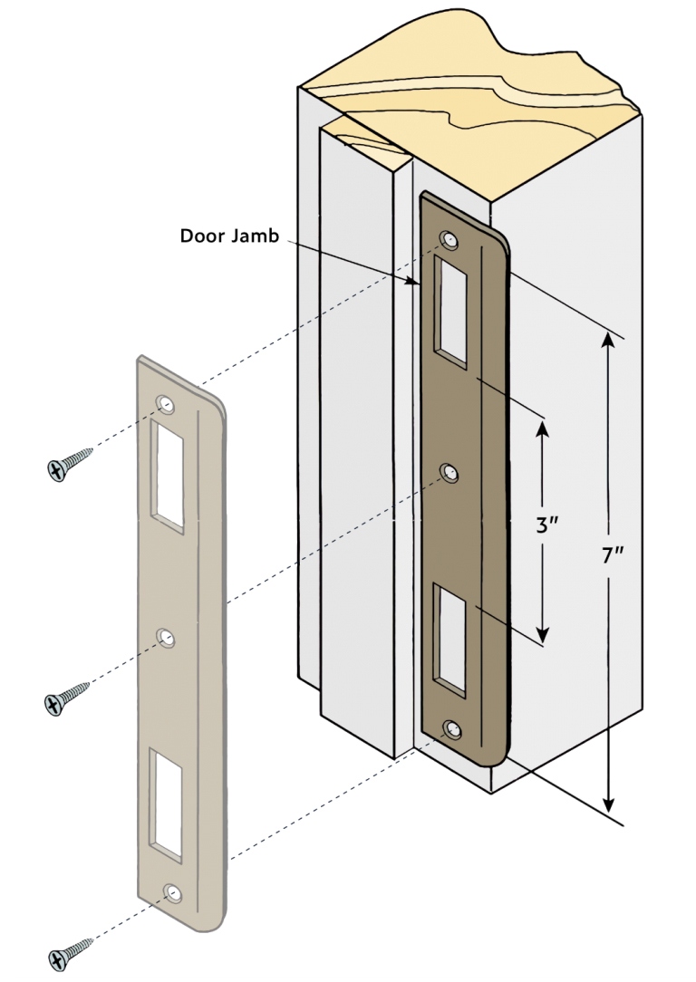
Close the screen door and mark the location of the latch bolt and deadbolt on the door jamb.
Step 7
To ensure that the latch bolt and deadbolt easily enter the door jamb when the deadbolt is in the locked
position, it’s necessary to remove enough wood from behind the strike plate. The strike plate should be
flush with the door jamb. Secure the strike plate to the door jamb using three of the supplied #8
self-tapping screws – Diagram 2.
Note: The radius of the latch bolt should face the inside door stop when the door is closed.
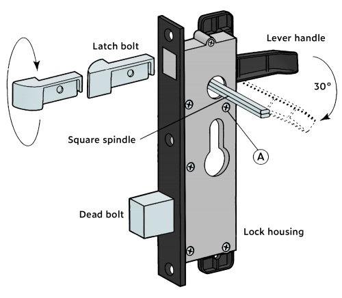
HOW TO CHANGE THE DIRECTION OF THE LATCH BOLT
The latch bolt may not be in the desired position because of right and left-handed swinging doors. Follow these steps to change the direction of the latch bolt.
Step 1
Disassemble the handle set.
Step 2
Press the lever handle down approximately 30 degrees and remove the single Phillips screw (A) – Diagram 1. Release the lever handle, so the latch bolt is now free to be
removed.
Step 3
Rotate the latch bolt 180 degrees as shown in Diagram 1. Press down the lever handle and reinsert the
latch bolt. While the handle is still depressed, replace and tighten the screw (A). Release the handle.